What is the input format for rotor profiles?
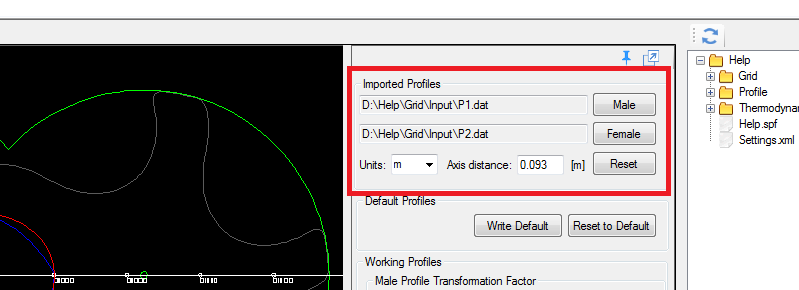
Rotor profiles are imported through User profile tab in form of data files.
Two data files need to be imported: Male profile and Female profile.
Data files may be from software that generates them, may be measured using CMM machine or from CAD model. The accuracy of the performance prediction will depend on the accuracy of the profile files and it is known that CAD generated files may introduce in the representation of the profile.
For more information please see online documentation
Can the User Profile be imported directly from CAD?
No, the user needs to extract data points from CAD system first and then to import data files.
The new SCORG® 3D viewer is coming soon and will include this function to import profile form CAD system.
For users of Solidworks a macro is available that can help in extracting profile points from CAD curves and exporting into MS Excel
What is the difference between User Profile and Generated Profile?
User Profile: These are profiles defined by point coordinates and imported into SCORG® Generated Profile: SCORG® has functionality to generate conjugate rotor profile pairs internally for specified geometrical parameters. This tool is available for special license and further details can be made available when you contact us
How to set the interlobe, radial and end leakage gap size for thermodynamic chamber model?
Interlobe gap size to be used for thermodynamic calculations is set in the Profile setup: GAPI
Profile –> Profile Setup
Radial and End Leakage gap size for thermodynamic calculations is set in the Machine configuration setup
Geometry –> Machine Configurations
Are real gas properties available for thermodynamic chamber model?
Not in release v5.1 but we plan to implement real gas in our future release to be used with thermodynamic chamber model
How to set the interlobe, radial and end leakage gap size for CFD rotor grid?
Interlobe gap size to be used for Grid generation is dependent on the imported rotor profile and is additionally set in the Profile setup as an incremental quantity: GAPI
Profile –> Profile Setup
Radial Leakage gap size for Grid generation is set in the Machine configuration setup
Geometry –> Machine Configurations
End Leakage gap size setting is not used by Grid generation
In what format is grid generated by SCORG available?
SCORG® Grid Generator can provide mesh files in ANSYS CFX, ANSYS FLUENT, Simerics Pumplinx and STAR CCM+ native formats
Node positions for successive time steps are available as simple ASCII files with (x, y, z) patch
What is difference between theoretical suction and discharge ports and the actual?
Theoretical ports use theoretical built-in volume ratio to generate the port areas and the flow passages are simplified geometries so that thermodynamic chamber models can be applied or good quality hexahedral mesh can be generated for CFD analysis
For multiple female rotor grid generation what are the inputs required?
You only need to change the number of gate rotors in Geometry>>Machine Configurations >> N Gate
Below is an example of two gate rotors configuration

What is the typical node count required for a CFD simulation of twin screw compressor?
There are three different grid spacings that can be controlled using SCORG® Grid Generator
Circumferential Divisions control the profile discretization.
Radial Divisions control the number of cells between the rotor and casing
Angular Divisions control the number of positions for which the mesh is generated and also the number of cross sections in the axial directions
Depending on the setting used for all these three parameters, a typical cell count in the rotor domain can go up to 2 million
Is it possible to place female rotor grid on the left or right side of the male rotor?
Yes this is possible. You can do this by changing the input in Geometry>> Rotor Configuration>>Gate Rotor Position
Below is an example of Left or right side gate rotor configuration
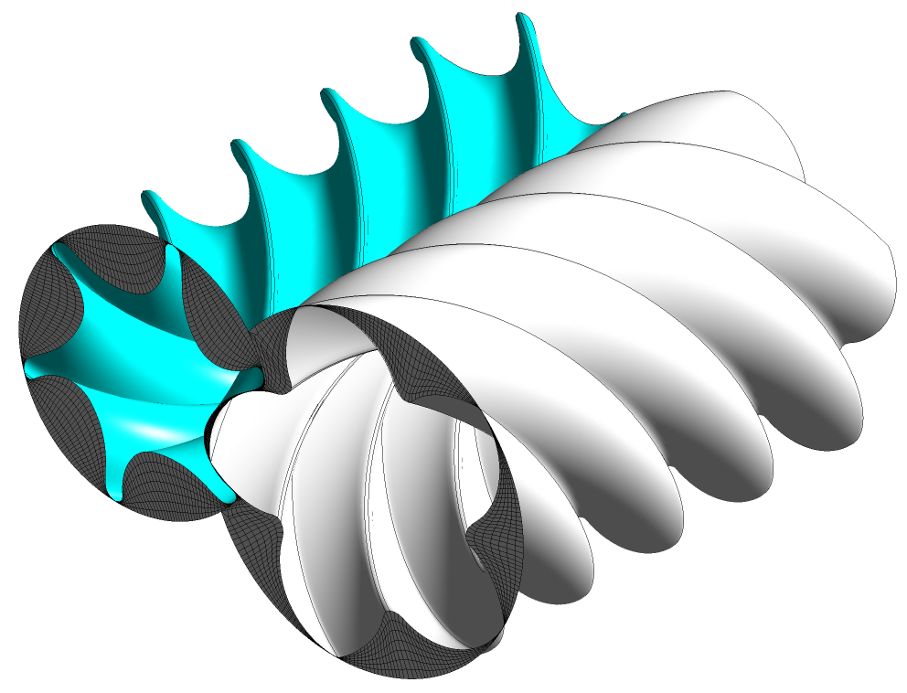
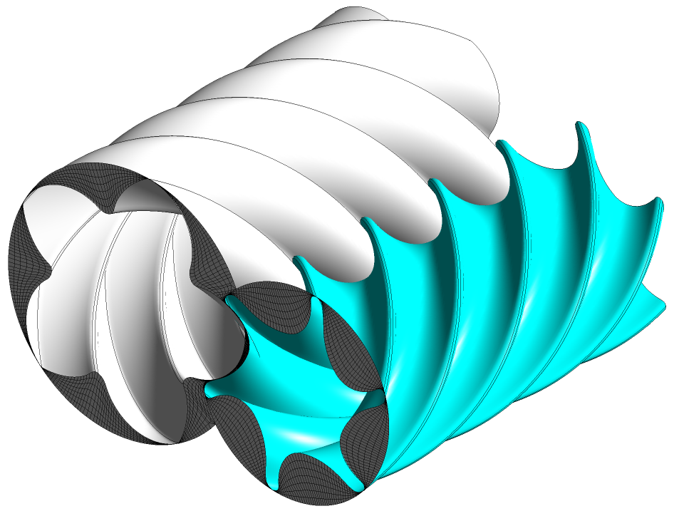
Is it possible to change the helix hand on the rotor grids?
Yes this is possible. You can do this by changing the input in Geometry>> Rotor Configuration>>Main Rotor Helix
Below is an example of Left or right hand Main rotor helix configuration
The Gate rotor will be automatically set